You put the Primary back together in the reverse of disassembly - inner case, engine sprocket, clutch and primary chain, rotor/stator, and last the outer case.
1) Check the engine sprocket key fits smoothly.
2) Insert the sprocket key into the engine crankshaft
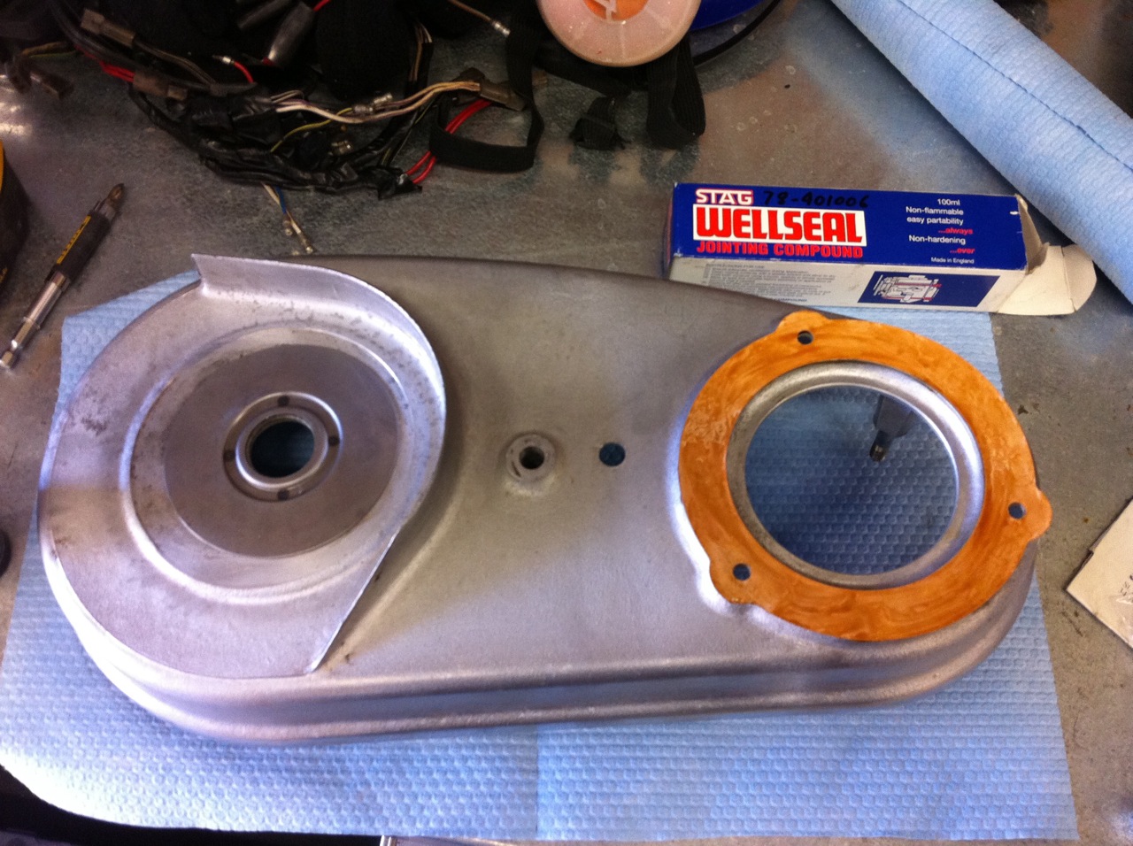
3) Place the inner case gasket on the case, holding it in place with a non-setting gasket compound. (Wellseal is what Mick Hemmings likes - so...)
4) Check the washer is on the support stud (Part No 000010). There might also be shims as well. (I forgot to take a picture of this, but my setup had one.)
5) Make sure the mating faces of the inner and outer case are clean and true.
6) Fit the inner case making sure not to damage the mainshaft seal and that the forward end is all the way home.
7) Fit the inner case tab washers and screws. Squeeze the washers over to lock in place. A dab of Loctite might be good too. The holes that these screws go into are through drilled to the crankcase. Therefore it is possible for engine oli to weep through here and sealing the threads can't hurt.
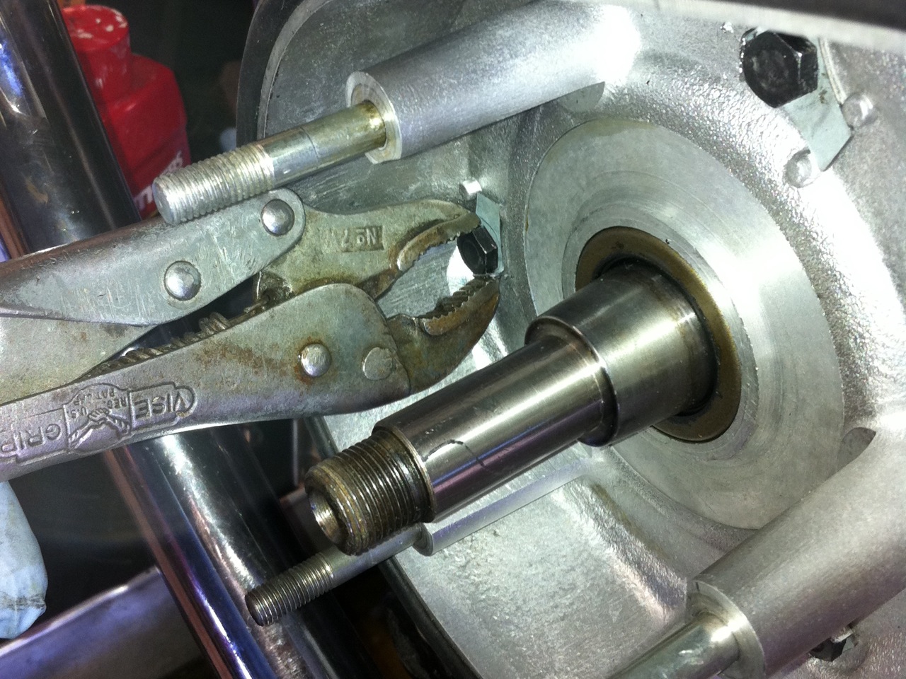
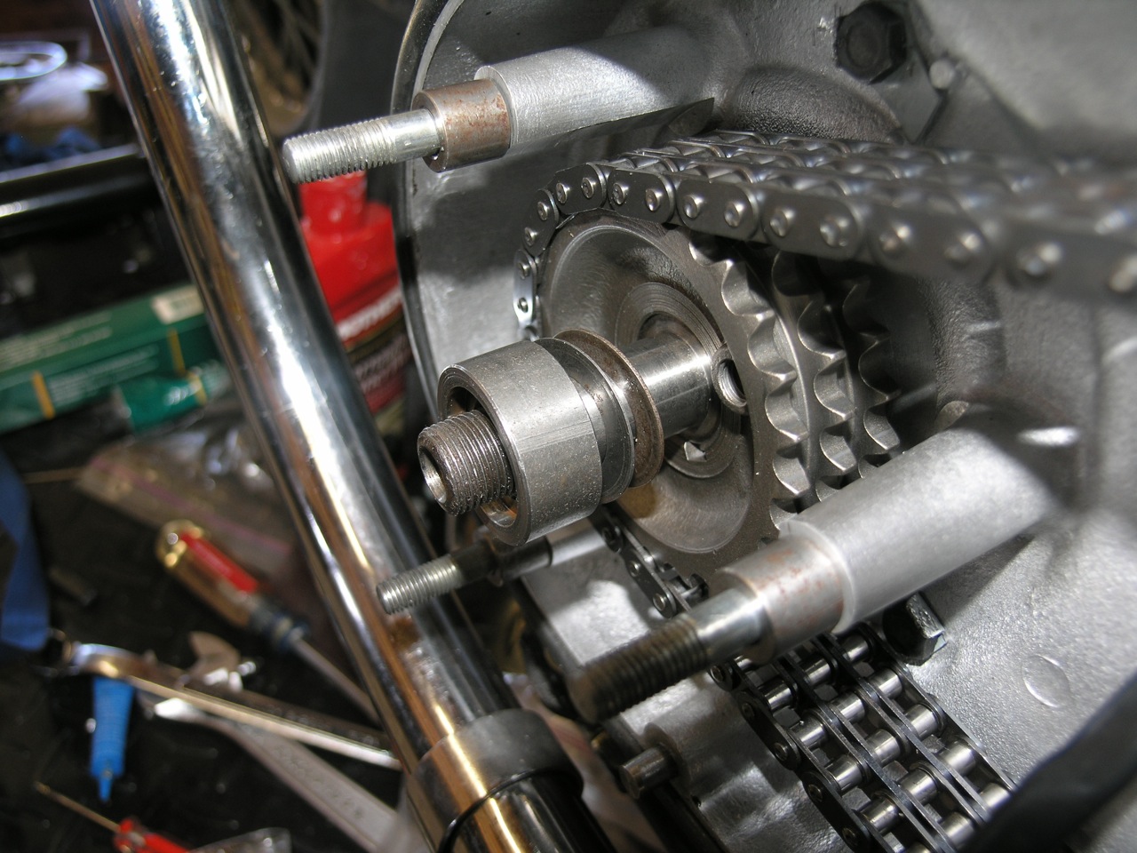
8) Assemble the clutch location spacer (Part No 060747) with the recessed portion TOWARD the gearbox. This should encircle the clutch location circlip (Part No 060752).

Hard to see - but the I'm installing a new clutch location circlip as my old one was overtorqued.) Install the circlip with the sharp inner edge facing the transmission.
NOTE: Jim Comstock recommends "The circlip on the 850 Mk3's starter idler shaft (Part No 06-8072) is slightly larger than the clutch circlip. If you take that circlip and sand a few thousandth from the thickness it fills the groove and is slightly larger in OD than the original circlip so it fits snugly in the relief in the washer. It is much stronger than the original clutch circlip and I have been installing them for years with much better results. I stick them to a 1 inch square "sanding block" with double sided tape and work them down slightly on a stone. It doesn't take much. Just until they are a snug fit in the groove. Jim
In my case I needed 3 shims to get the alignment needed.
NOTE: The manual indicates that you should torque the clutch fixing nut to 70 ft/lbs. This is excessive as it tends to shear the location circlip. If you believe the clip has seen torque values higher than about 40 ft/lbs - replace it now. If in doubt replace it.
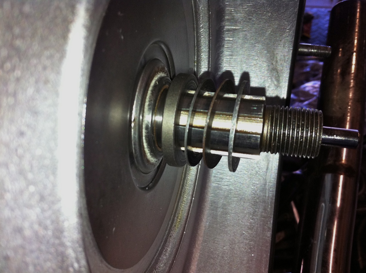
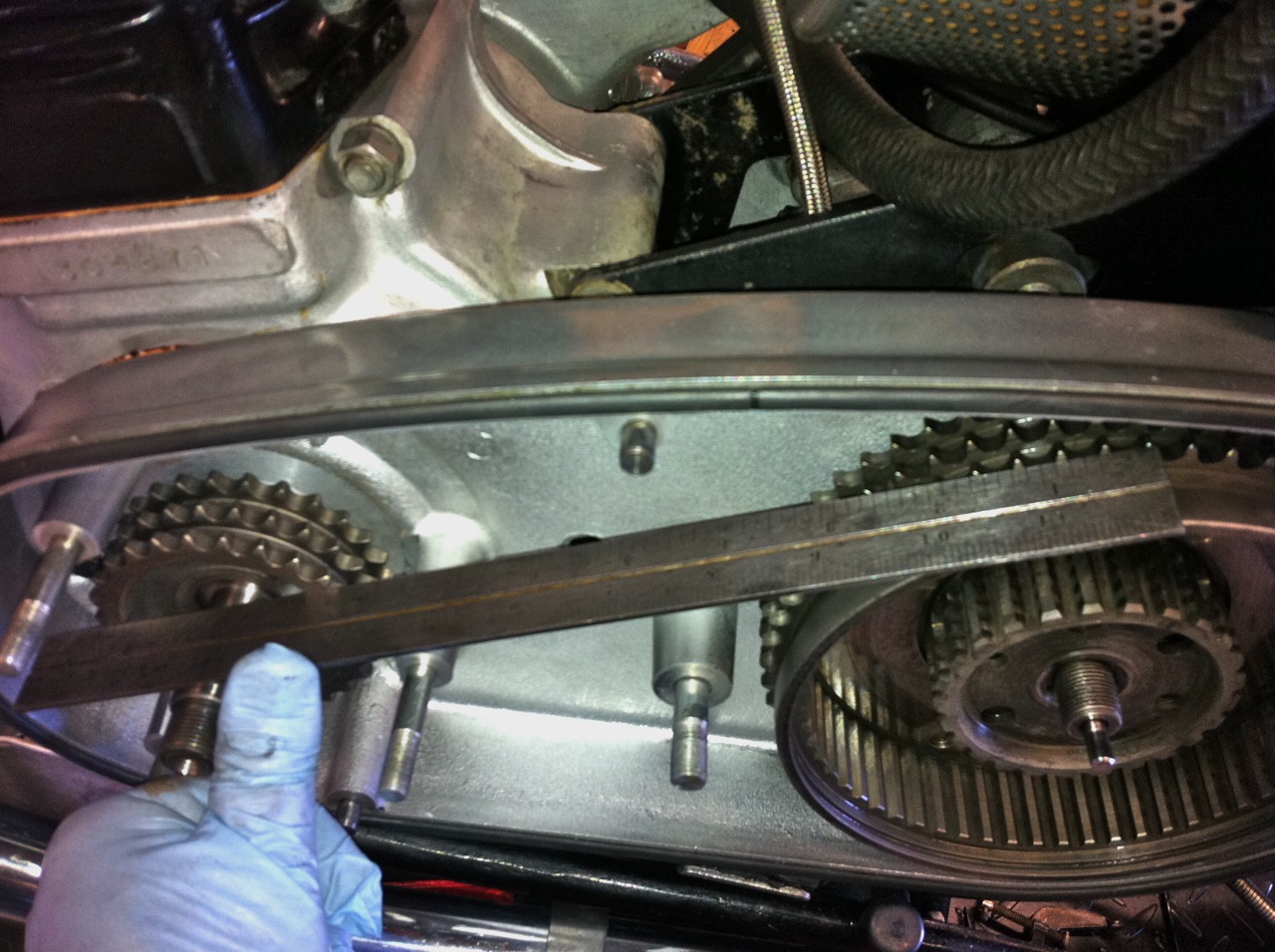
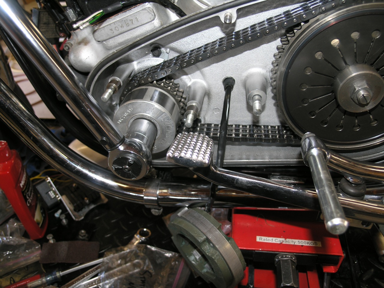
Follow the spacer with the proper stack of location shims. These shims determine the alignment between the clutch sprocket and the engine sprocket. Use a straight edge to make sure these sprockets are in the same plane and running true.
9) Wrap the triplex chain around the clutch sprocket and engine sprocket prior to fitting.
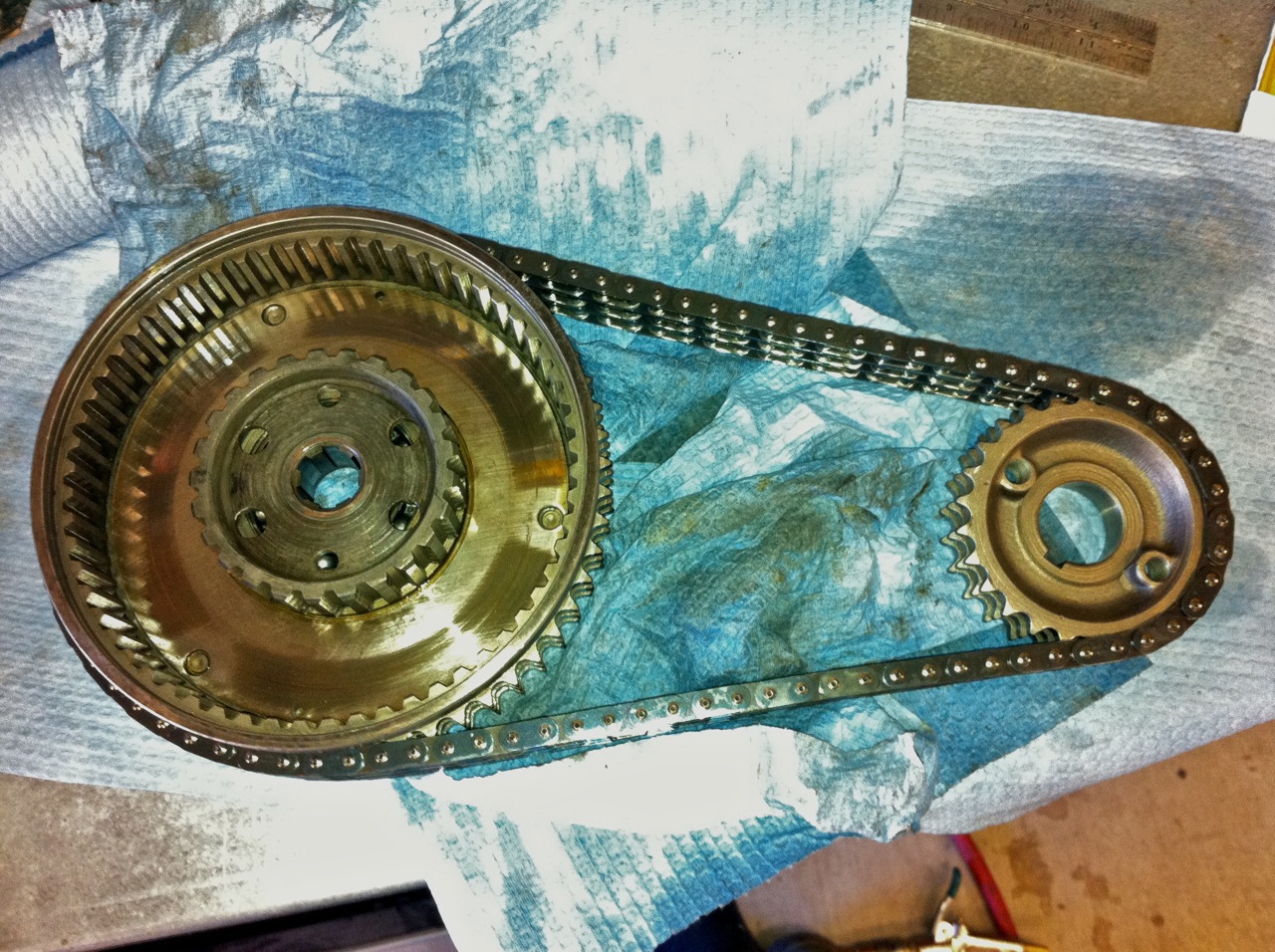
10) Offer all three (clutch sprocket, engine sprocket, chain) as a set, remembering to get the stator between the chain runs (If the stator is still attached.)
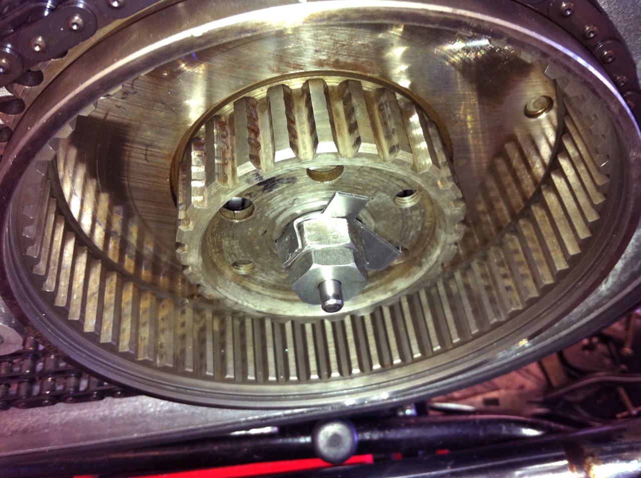
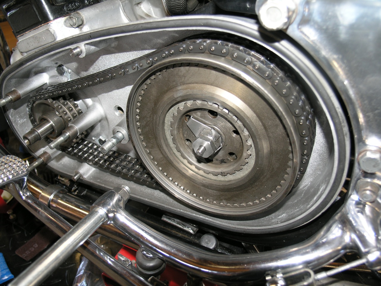
11) Push both sprockets home. Make sure the engine sprocket is fully home and over the woodruff key.
12) Fit the clutch securing nut, washer and tab washer. Make sure the tab washer engaging ends are in the 2 holes in the clutch basket.
13) Loosely mount the rear brake pedal and footrest use the brake to tighten the clutch center nut.
NOTE: The manual calls for 70 ft/lbs. This is generally recognized as too much for the poor little circlip. It's recommended that you use blue Loctite and go to 40 ft/lbs on a NEW circlip.
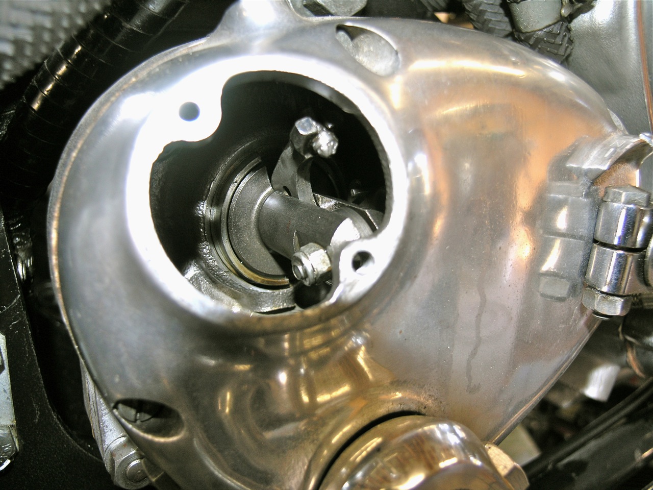
NOTE: Shown is the DynoDave clutch push rod seal in place at the end of the input shaft. For reliable smooth operation of the clutch, the clutch plates need to be free of gearbox oil. Unfortunately the Norton design allows oil to weep down the clutch push rod. There are various approaches to fixing this, but the DynoDave clutch rod seal seems teh best to me. I can recommend it. - a worthwhile upgrade. You can find out more about it here - http://atlanticgreen.com/store.htm.
14) Replace the clutch plates with an inner splined friction plate first.
NOTE: For optimal clutch operation, you need to set the stack height. Old Britts has a great article on this here - http://www.oldbritts.com/ob_clutch_info.html
15) The clutch diaphragm spring should already be tensioned on the spring tool as shown in Fig C13 until it is flat.
16) Offer the diaphragm spring to the clutch
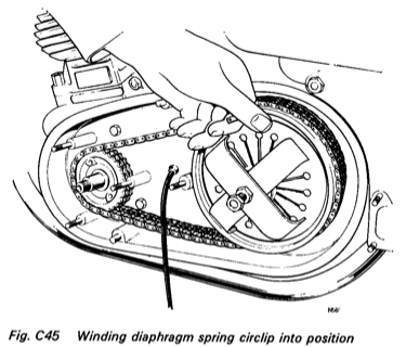
17) Place on end of the spring circlip (the big one) and wind it into the housing.
18) After making sure the spring circlip is fully seated, remove the spring tool by loosening the center bolt.
19) Fit the clutch push rod adjuster screw and lock nut.
20) Adjust the clutch push rod with the handlebar adjuster until there is just lift on the diaphragm spring, then back off one turn.
NOTE: It is possible (and probably likely if you've removed the clutch pushrod), that clutch operating lever in the gearbox outer case (right hand side of bike) has dropped down. You'll have to remove the inspection cover to get at this. This will basically render the clutch inoperable. You need to make sure it's in the correct position. If it's fallen down, loosen the cable all the way, move it back into position, then readjust.
This picture shows the lever in the correct position.
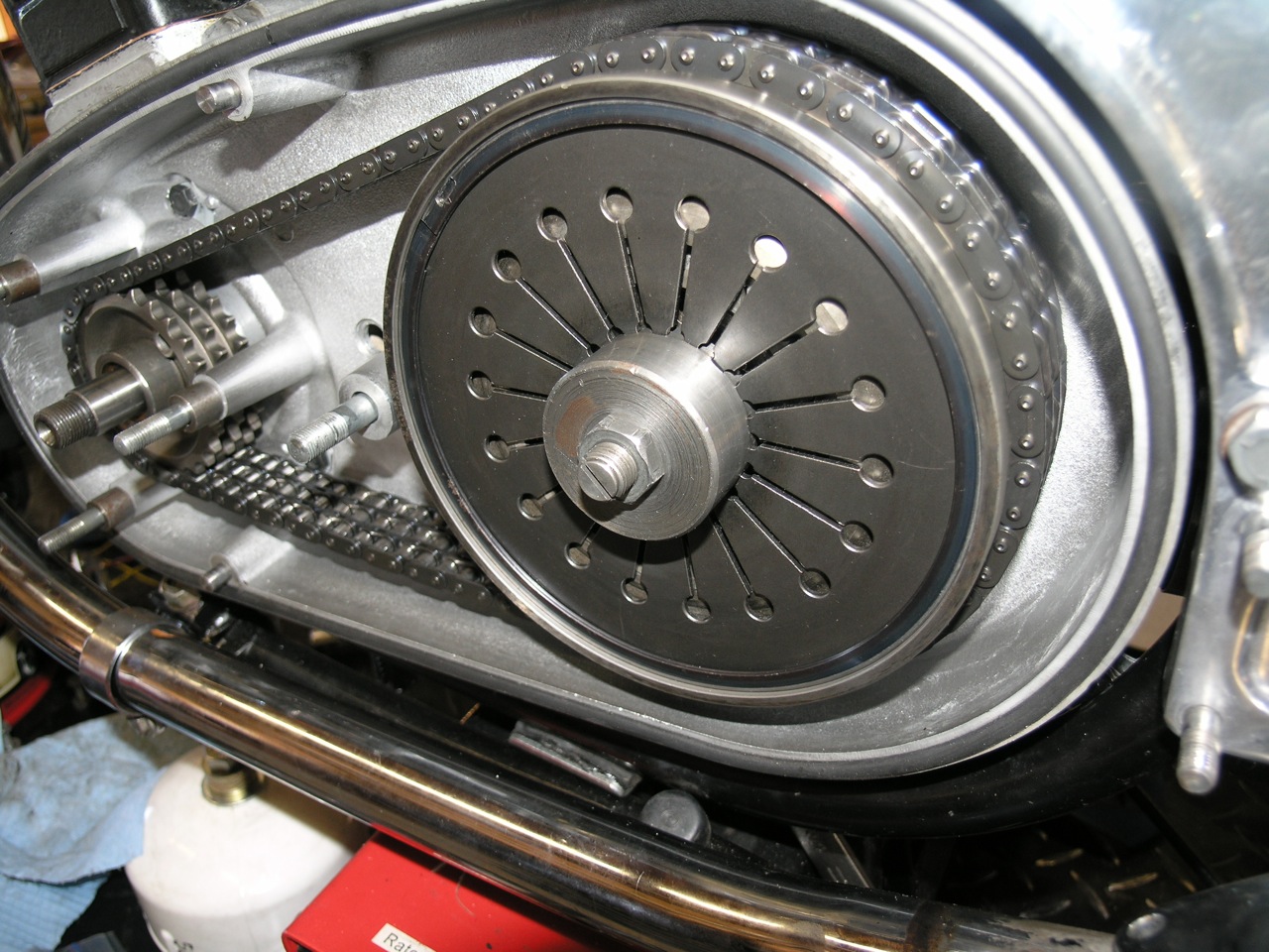
21) Assemble the shims on the crankshaft over the engine sprocket. Follow with the spacing collar (Part No 060402) - recess outwards.
22) Fit the rotor key. The end of this fits into the recess on the spacing collar.
23) Fit the rotor. Make sure no metal chips are stuck to it. Name and timing marks should be facing out (duh).
24) Assemble the rotor not and fan washer while in top gear and the rear brake fully applied. Tighten to 80 ft/lbs. I like a bit of blue Loctite here too.
25) Put the 3 stator spacers on the studs, then mount the stator. The output leads must be in the 5 o'clock position.
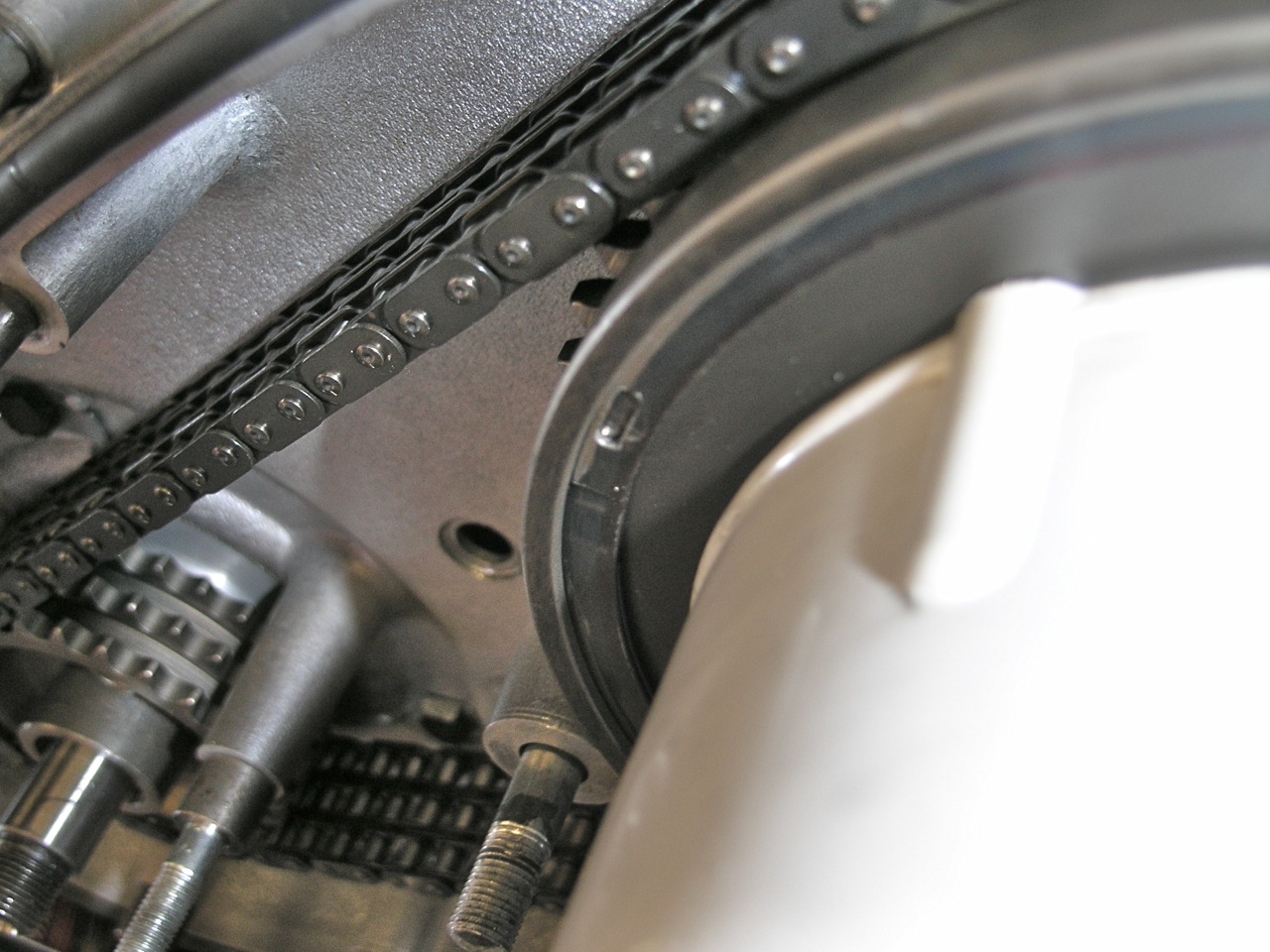
NOTE: Now's a great time to check and adjust the Primary chain - (See C41 - Chains)
26) Assemble the washers and stator nuts - torque to 15 ft/lbs.
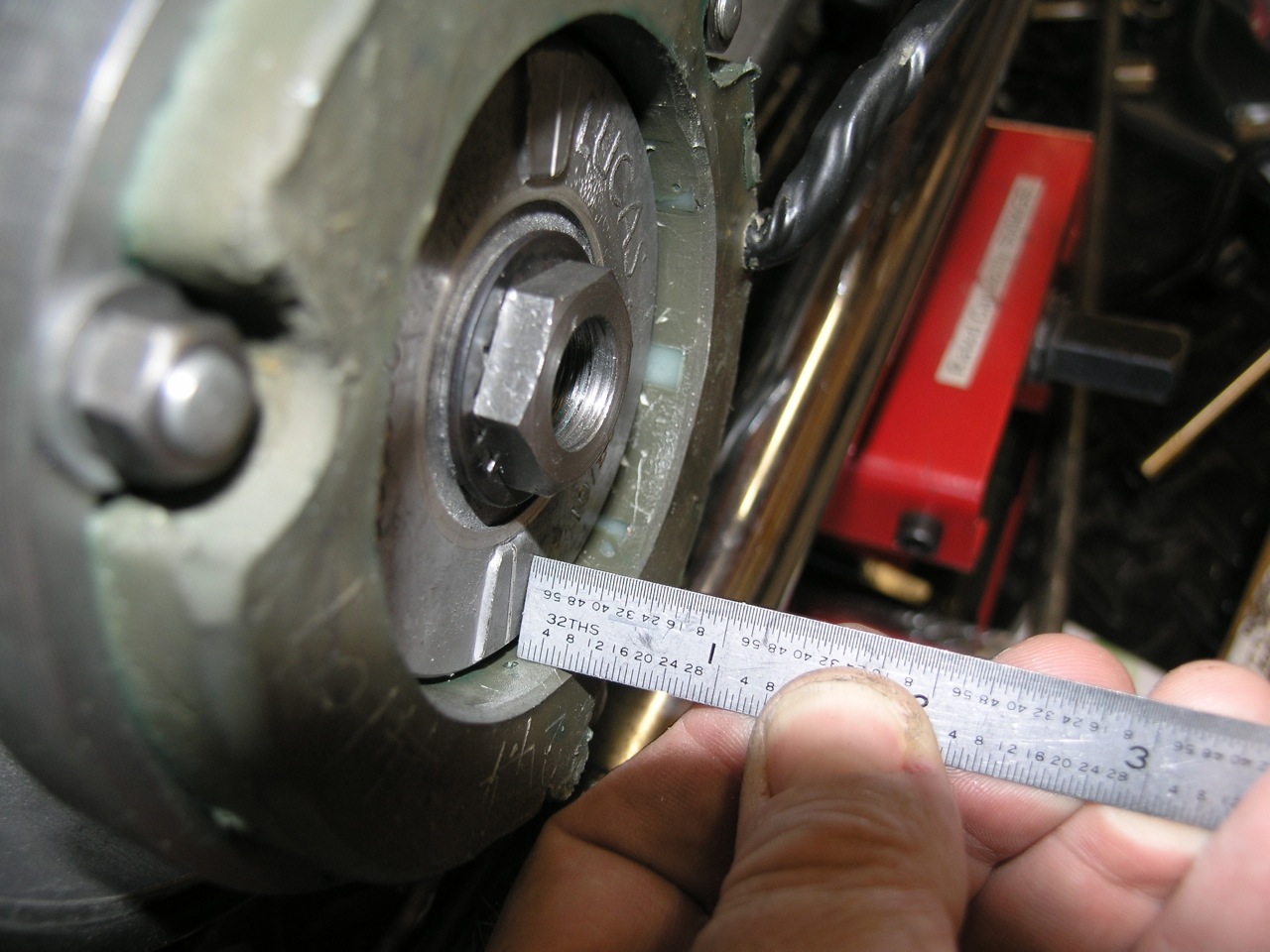
When I initially installed the new unit I found the rotor was quite recessed - around 5/16". The general consensus was it was "OK" but didn't really look right. After a lot of measuring (old and new), I decided that way to fix this was to get some shorter spacers. The original ones were 0.490 and I turned some 0.305 ones. I guess this is called "fettling". This was much more acceptable.
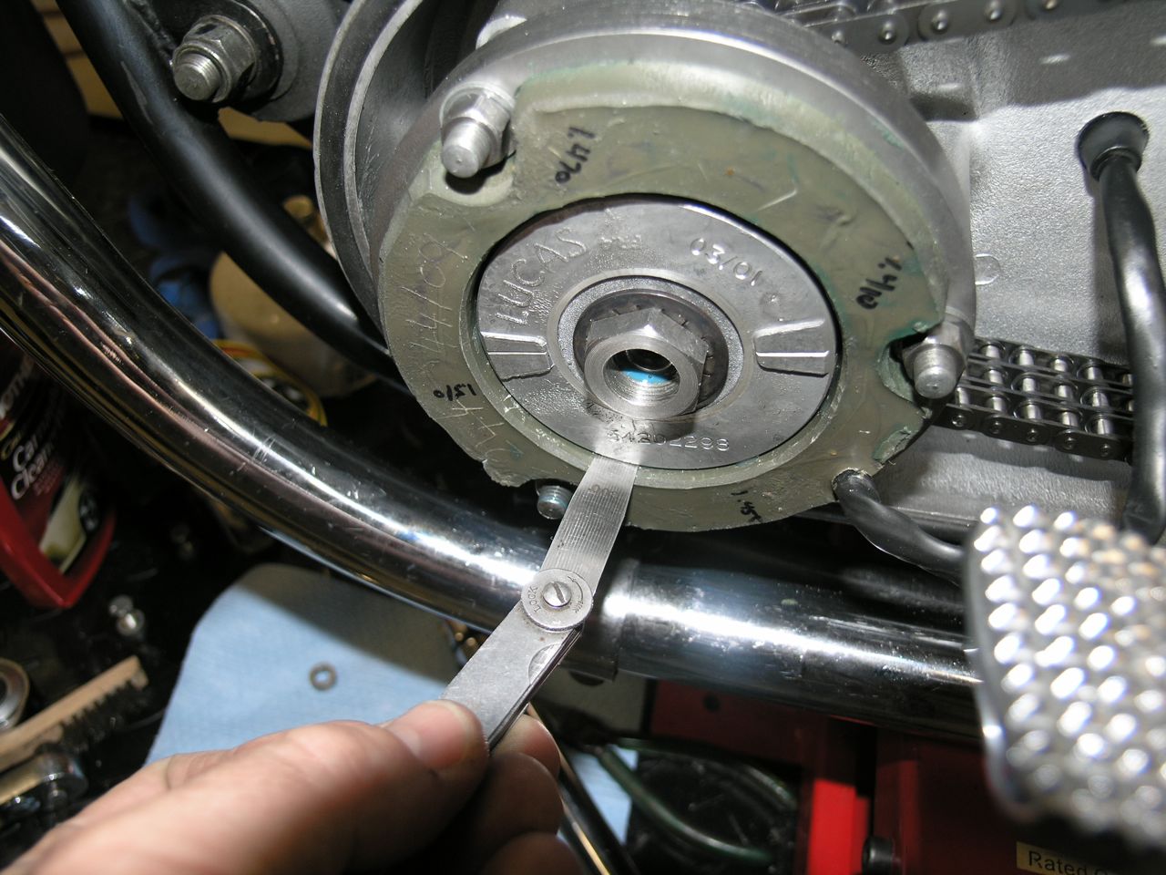
Check the air gap between the stator and the rotor. It should be no less than 0.008 to 0.010". The manual indicates you should "re-align" the studs to achieve this. I think they mean to bend them. Others have enlarged the stator mounting holes to allow for adjustment. However you do it, it's important. If the gap is too small, then rotor will hit the stator especially when things have expanded when hot and due to vibration.
27) Mount the sealing band (big rubber band thing) in the inner cover. I usually add a bit of gasket sealing compound to this side to hold it in place and provide a better seal. The join in the band should be at the top. It's worth making sure the band is evenly depressed in groove and that the sealing faces of both the inner and outer are clean and true.
NOTE: Now is a great time and highly recommended to double check your new timing mark on the rotor with your primary cover. I found mine was about 4 degrees off. Here's how I did it.
28) Attach the outer case (which you've polished of course) with the center nut and washer. Don't over tighten as it might warp your case.
29) Add oil the primary at this point.
NOTE: I've found that pre MKIII primaries run best with ATF. You get two benefits - 1) ATF doesn't affect the clutch plates, and 2) the red color helps you track down leaks.
30) Refit the left hand foot rest and brake cable. The stop lamp lead support acts as the third washer on the bottom stud.
NOTE: Brake Return Spring Upgrade. There is an aftermarket spring that you can add to the brake lever as a safety in case the brake cable breaks. If it did, the lever will droop down and contact the pavement - pogoing you and bike. This spring will keep the lever in an upright position. This is recommended to mount.